
Hrd67 hardfaced wear components for paste backfill reticulation and abrasive service.
Complex chromium carbide weld overlay — a ¼" deposit, double pass, applied end to end through the coupling zone — 3/16" on fabricated components and bulk stock at 3" nominal. Three supply routes, one part numbering system, one specification.
The deposit runs under the coupling. A bare band at every joint would become the governing wear location on the line.
Five things to know before you order.
Published range 3" SCH 80 to 24".
SCH 80 is the small-bore substrate — it is what carries a double-pass deposit at 3", 4" and 6". At larger bores the drawing names the wall for the size. Substrate is A106 Gr. B seamless or A53 Gr. B carbon steel, named on the drawing for every part number.
26" and 30" XS on special request. On free-issue material, minimum accepted wall is 0.250" measured — see the acceptance note below.
| Bore | Substrate wall |
|---|---|
| 3" | SCH 80 — 0.300" |
| 4" | SCH 80 — 0.337" |
| 6" | SCH 80 — 0.432" |
| 8" | 0.500" |
| 10"–24" | Named on the drawing at quotation |
Pick the route by what you already hold, not by what a catalogue sells.
Same consumable, same ¼" nominal deposit on all three — 3/16" on fabricated components and bulk stock at 3" nominal, the applicator maximum for 3" stock. What changes is who supplies the steel, when the grooves get cut, how the deposit is laid down, and which geometries are on the table. Lead times are quoted per order.
Fabricated complete components
Built from straight stock overlaid under rotation, cut and joined to geometry, cut grooved as the final operation. The substrate is specified, not inherited.
- No groove ever sees weld heat. Grooves are created last, on the finished part, and conformance is established before shipment.
- Geometry you cannot buy as a casting. 66°, 37°, 35.6° — any angle, drawn and numbered.
- Interchange stated on the drawing. Each sheet names the Victaulic figure its envelope matches, if applicable — a change-out is a fit decision, not a guess.
Free-issue overlay service
You free-issue a fitting from your own stock; OPC overlays the bore and returns it. Deposition is longitudinal, balanced sequence — opposing beads cancel each other's contraction, preserving groove geometry and end dimensions through the overlay.
- No new material master, no new stock line. The part is one you already carry.
- It reaches components OPC does not fabricate. Reducers and the compact geometries outside the fabrication range carry Hrd67 through this route — any piece that needs protecting can get it.
- Don't stock the fitting? OPC will source it. Source, supply and overlay on one PO — the same route without the free-issue step.
- Every piece measured at receiving against SPEC-HRD67-BM — wall by UT or calipers, not by eye.
Bulk overlaid stock
Overlaid straight pipe, ungrooved, plain end — 4 ft, 6 ft, 8 ft and 10 ft 6 in at 4" and above; 3" bore in 4 ft lengths only, at 3/16" (the applicator maximum for 3" stock). You cut to length and cut groove on site.
- Make the pup you need, the shift you need it. Once the stock is on your shelf there is no lead time on a four-inch spool.
- Order the longest length the position allows and cut to requirement.
- Cut by plasma or diamond blade; cut groove only — never roll groove. A ¼" chromium carbide deposit has no ductility and will crack and spall at a rolled groove.
Line survey and wear mapping
A component-by-component record of the line: every bend, tee, reducer and spool — angle, size, schedule, position in the flow sequence, and the wear point at each, photographed against a position reference.
- Where a site has no isometric for the line, the survey produces the record — instead of the knowledge living with whoever last did the changeout.
- It is your document. The quoting basis, the spares schedule, and a record a new planner can work from.
- Supplied as part of component supply. Not a separate engagement and not billed as one.
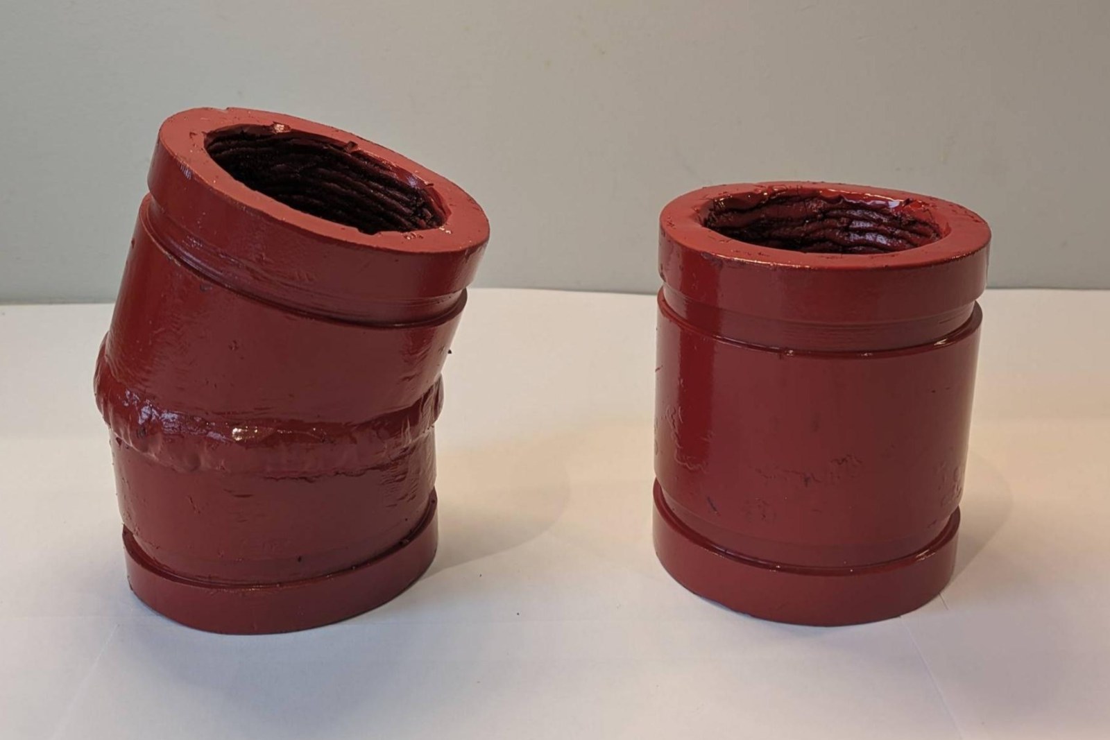
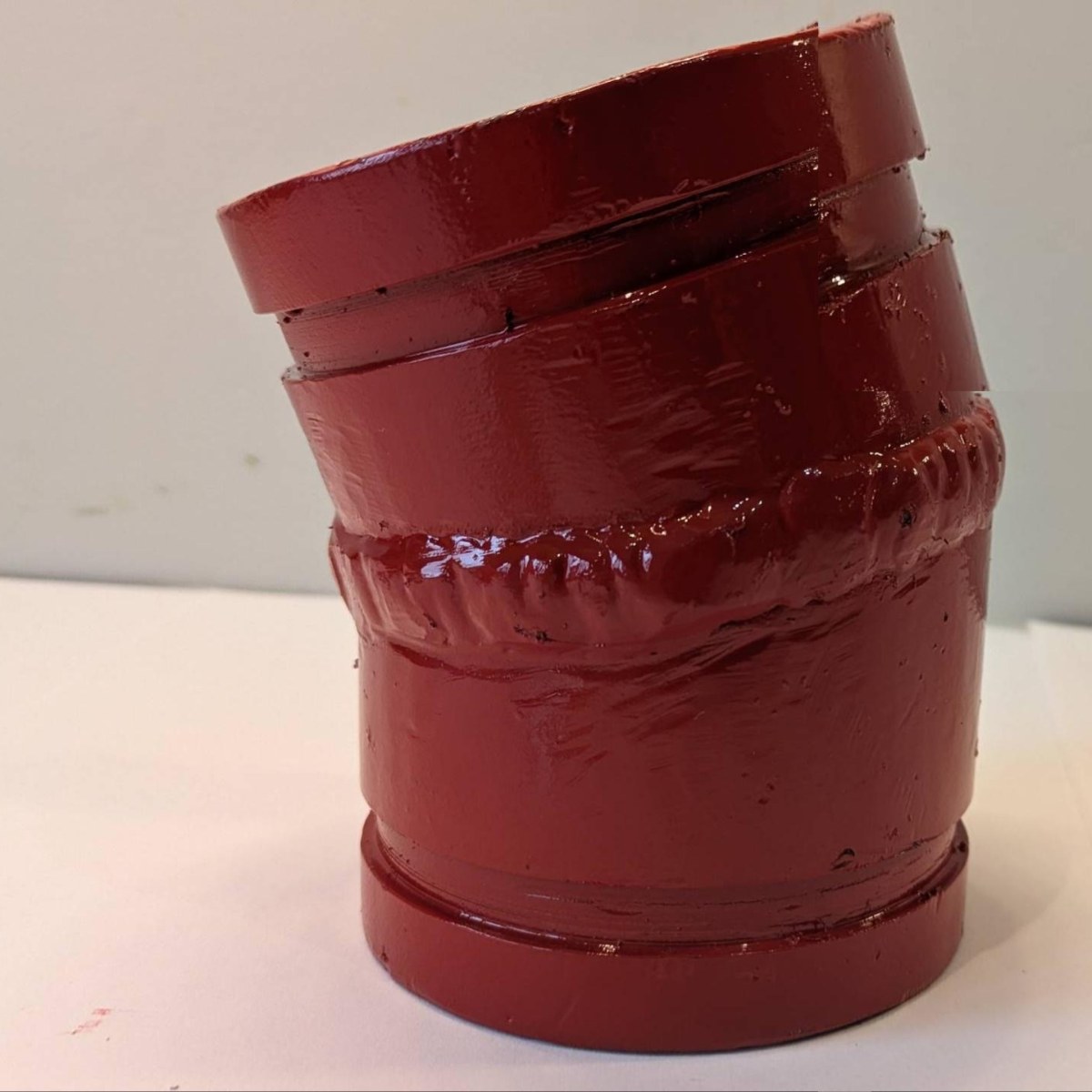
The same two positions as the Route 02 panel, built as complete components: a 3" 22.5° compact elbow (OPC-BF03-022MCVG) and a 3" × 4" spool (OPC-BF03-SPOL04VG). Overlaid stock, cut and joined, grooved last.
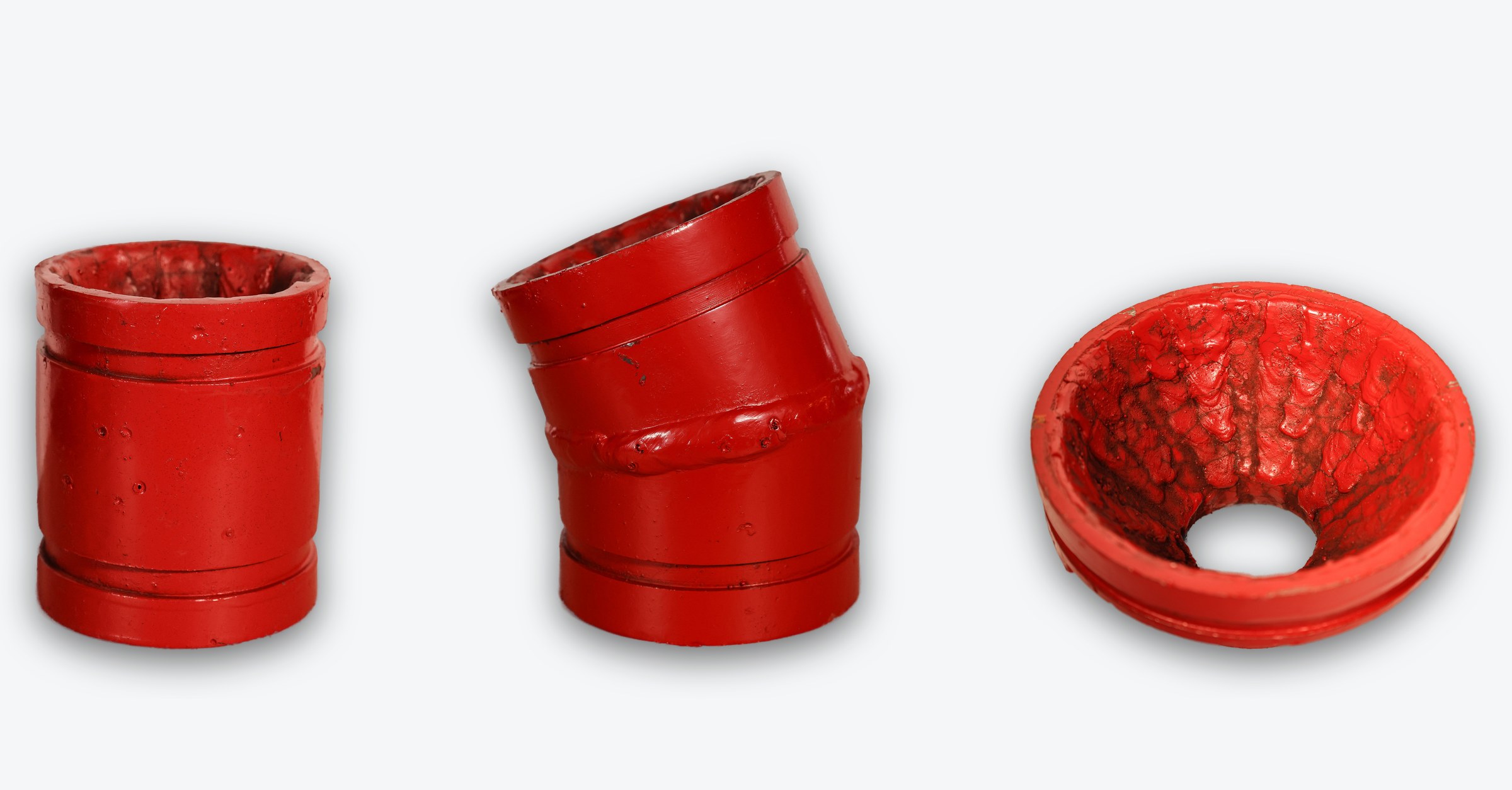
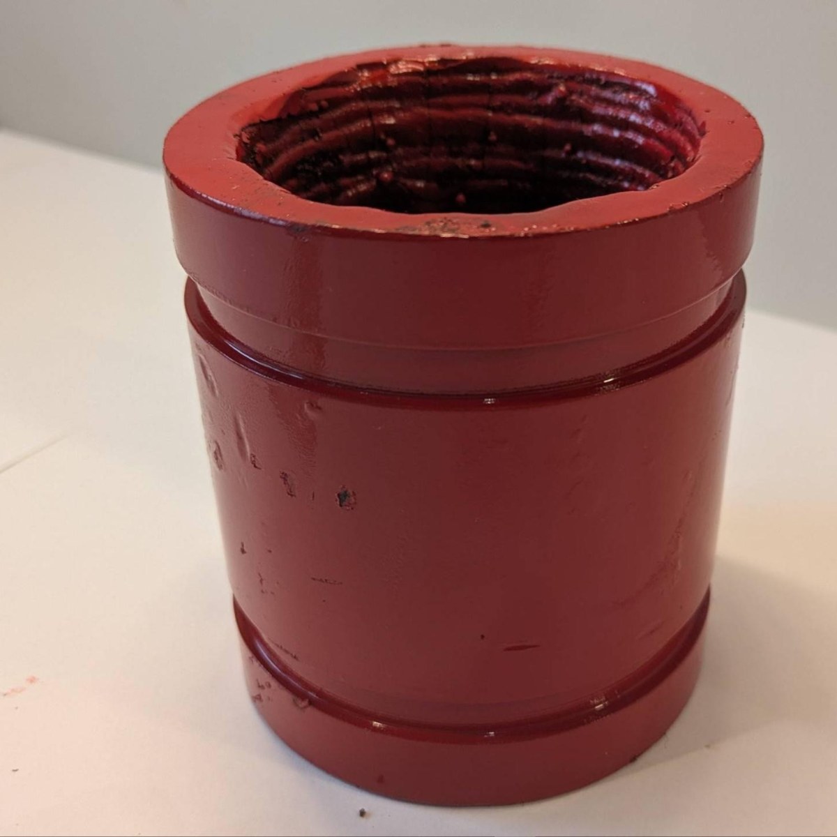
Standard grooved fittings, free-issued and returned overlaid — a 3" × 4" stub, a 3" 22.5° elbow and a 6×3 concentric reducer. Hrd67 across the full interior, end to end; grooves and gasket seats left bare.
Stated precisely: same Hrd67 consumable and ¼" nominal double-pass specification on both routes, laid down differently. Fabricated components and bulk stock at 3" nominal carry 3/16" — the applicator maximum for 3" stock; a free-issued 3" fitting takes the full ¼". OPC makes no comparative wear-life claim between the two.
| Free-issue overlay — SV | Fabricated component — BF | |
|---|---|---|
| Substrate | Whatever was bought — commonly a standard-wall casting. Verified on receipt, not chosen | Specified: SCH 80 at the small bores, the wall the drawing names above, chosen before the first bead |
| Deposition | Longitudinal, hand-sequenced in a balanced pattern — chosen to protect grooves that already exist | Circumferential on rotated stock — continuous, fewest starts and stops, more consistent coverage |
| Rejection risk | Real. Under 0.250" measured, or grey iron, comes back uncoated | None. The substrate is OPC's to get right |
| Choose it when | You hold it, or OPC does not fabricate it | A custom angle, or a repeat-failure position |
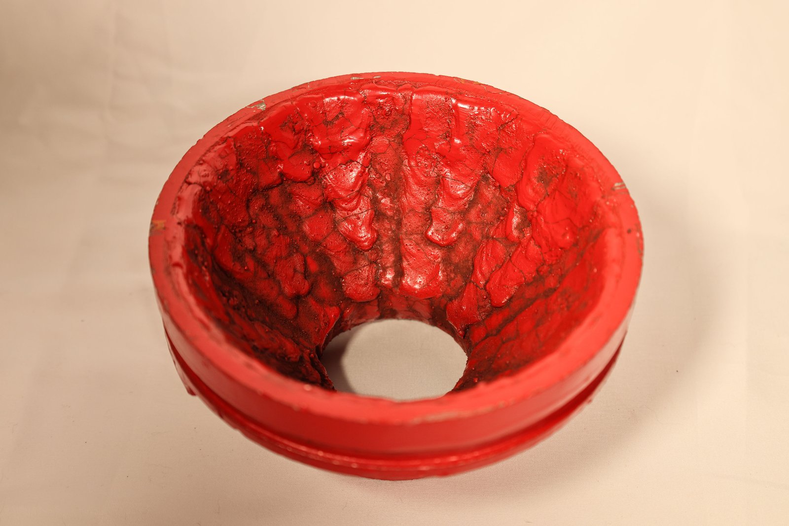
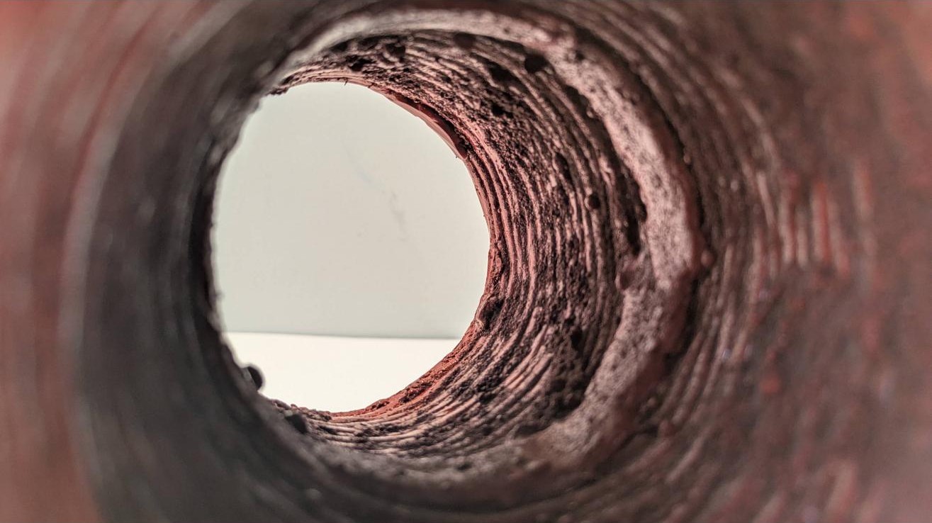
Inside a free-issued 6×3 reducer: longitudinal, balanced-sequence beads, as-deposited. The red enamel in the bore is temporary — it keeps the deposit from rusting between the shop and the line, and the first slurry through takes it off.
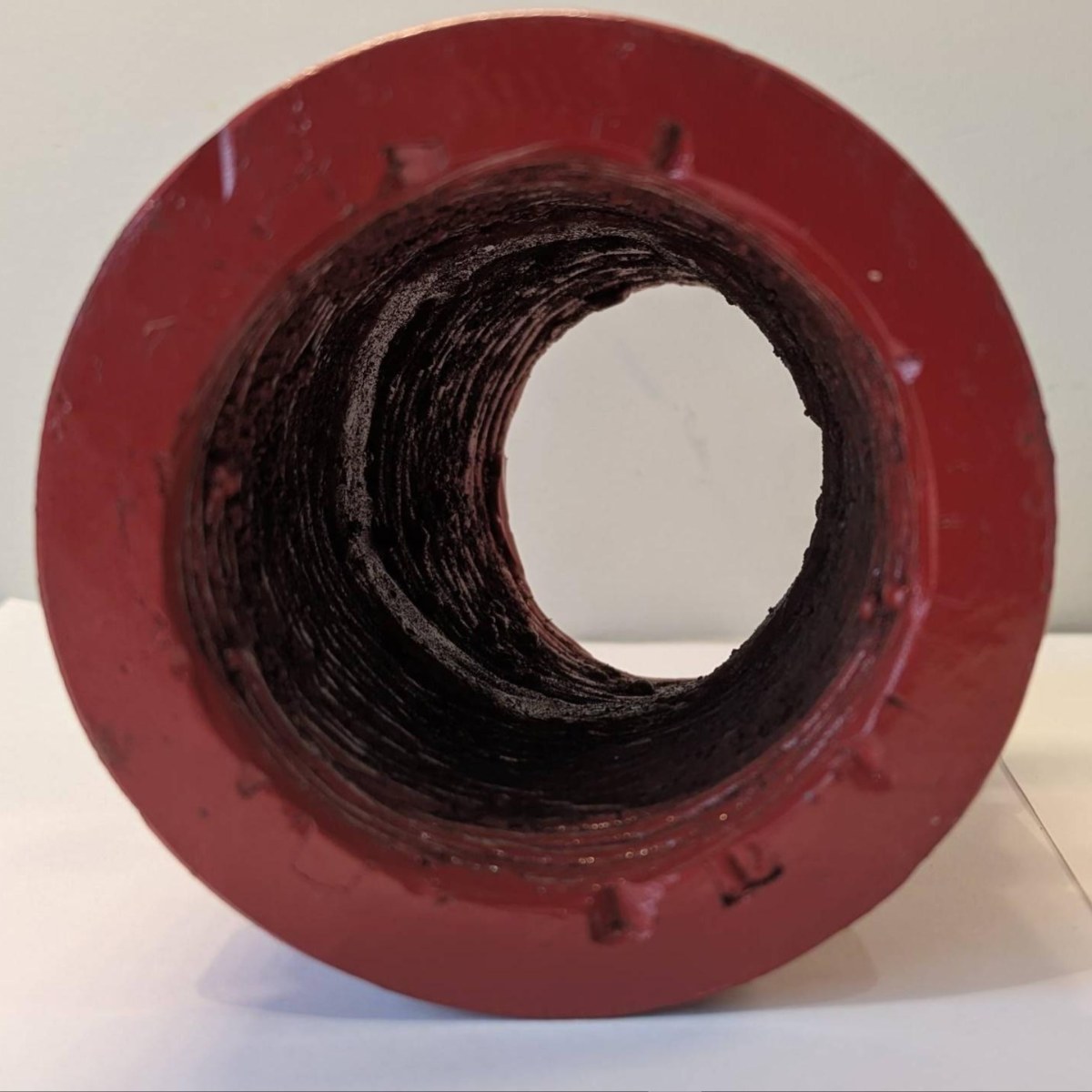
Inside a fabricated 3" 22.5° elbow: circumferential deposit laid on rotated stock before the part was cut and joined, seen bare before the enamel seal. Two routes, one deposit — the bead pattern is the tell.
Read before you free-issue anything
Wall governs. Minimum 0.250" measured wall — a double-pass deposit burns through anything thinner. Measured at receiving by UT or calipers on every piece, at every size; mill undertolerance runs to −12.5%.
Base metal. Cast carbon steel (A216 WCB) accepted without condition. Ductile iron at the applicator's discretion — there is no nickel buffer layer. Grey cast iron is rejected.
Full acceptance specification SPEC-HRD67-BM, current revision, and product data sheet PDS-HRD67 — on request.
Put a part number to it.
Every component is drawn, numbered and repeatable — see the component quick reference, or send the position and OPC will quote against it. When one wears through, read the worn part before it goes to scrap.